Appendix A: Monitoring Multiple VLANs
Monitoring Multiple VLANs
The Pulse infrastructure provides an adaptable hardware and software interface to ensure that your networks can be properly scanned to fingerprint assets and identify risks and threats, regardless of how a network is segmented. This document describes best practices for monitoring multiple VLANs with a Pulse sensor.
Best Practices
A network separated into multiple VLANs can be monitored using Pulse sensors. By configuring a trunk port—tagged for traffic for each of the VLANs to be monitored—the Pulse Sensor can conduct both passive detection and active scanning across all networks it can access to identify risks and threats.
In order to ensure proper operation, the following considerations must be met:
- Regardless of how many subnets will be monitored, a Pwn Plug Sensor can scan/monitor up to 1,024 network hosts, while a Pwn Pro can be used to scan up to 4,096 network hosts.
- If the number of network hosts exceeds the maximum scanning number of the Sensor, then multiple Pulse Sensors should used. Each Sensor should be deployed on a trunk port that is tagged with unique subset of VLANs to distribute the network asset count across the Sensors. This is to prevent two or more Sensors from scanning the same network hosts (thus exceeding the maximum number of assets to be scanned).
When scanning a subnet, the Pulse Sensors discover and fingerprint wired devices in two ways. First, the PwnScan service will actively probe and scan the network to discover new hosts and maintain its awareness of the environment. Next—on an hourly basis—the PwnScan service will initiate an active Port and Service scan for each host to discover open ports and enumerate the services running on those ports. The second discovery method involves passively listening for ARP Requests—indicative of when a new device joins the network—providing near real-time identification of new hosts. These new hosts will then be reactively scanned with an active Port and Service scan.
For customers that have specific subnets in a VLAN that require additional monitoring coverage, additional Pulse Sensors should be added to the system, dedicated those particular subnets, to ensure that ARP Requests are seen in real-time.
Setting up the Environment
This guide assumes the switch being used has already been configured 802.1q trunk port, and that the appropriate VLANs have been configured and tagged.
Note
It is important to ensure that the Native VLAN is set to the VLAN (eth0) the sensor will use to provide connectivity to Pulse via the web. Failure to do so could cause disruption or loss of access to the sensor.
Configuring Your Pulse Sensor
To allow for the PwnScan service to monitor the VLAN environments, the sensor must be configured with a sub- network interface for each specific VLAN. This is accomplished by modifying the interfaces file on the Pulse Sensor as follows:
- Log directly into the sensor via an SSH session using a command line tool. See Pulse Quickstart Guide for more detail on logging directly into a sensor using SSH.
- Establish superuser access by entering
sudo su, and authenticating with the sensor’s local password. Prior to modifying any configuration file it is always recommended to create a backup. To create a backup copy of the interfaces file, enter the following command:
# cp /etc/network/interfaces /etc/network/interfaces.bak
This creates a copy of interfaces in the same directory called interfaces.bak that can be used to restore if necessary.
Open the
/etc/network/interfacesfile in your preferred Text Editor (vi, vim, nano, etc.):# vi /etc/network/interfaces
You will then be presented with the current network interface configuration for the Pulse Sensor.
# vi /etc/network/interfaces

auto lo
iface lo inet loopback

auto eth0:1
iface eth0:1 inet static
address 192.168.9.10
netmask 255.255.255.0

### DO NOT EDIT THIS LINE OR BELOW
allow-hotplug eth0
iface eth0 inet dhcp
Above the line that says “
### DO NOT EDIT THIS LINE OR BELOW”—add an interface definition for each of the desired VLANs. Below are examples for how to configure VLAN interfaces for networks using a static IP addresses.Note
It is required that each network interface be assigned a static IP address. The use of DHCP for this configuration is not supported.
auto eth0.1
iface eth0.1 inet static
address 10.0.0.1
netmask 255.255.255.0
vlan-raw-device eth0

auto eth0.2
iface eth0.2 inet static
address 10.0.1.1
netmask 255.255.255.0
vlan-raw-device eth0
Note
It is important that these additions be inserted above the line that states “### DO NOT EDIT THIS LINE OR BELOW”. Anything written below said line has the chance of being removed.
Once the interfaces file has been properly configured with all desired VLAN information, the file should be saved.
The final configuration step is to bring up each the newly defined interfaces to enable them. To do so, run the following command for each of the defined VLAN tagged interfaces:
# ifup eth0.xx
Replacing xx with the VLAN tag. Using Examples 1 and 2 shown above, the commands to bring up their respective interfaces would be:# ifup eth0.1 # ifup eth0.2
At this point, the user should not modify IP addresses or network configuration settings from the Insight (local Sensor UI) Web Interface. All further configuration changes should only be made by directly editing the /etc/network/interfaces file.
Once the file has been saved—and all interfaces have been brought up—reboot the Sensor for the changes to take effect.
Once the Sensor has rebooted, log back into the Sensor using SSH and confirm using ifconfig command that all VLANs are being seen correctly - that each VLAN has a virtual interface such as eth0.X for vlan X , as well as an IP address (which may not show immediately if dhcp is being used).
Monitoring With Pulse
Once the VLAN interfaces have been added (as outlined above) and the sensor rebooted, the PwnScan service will need to be configured to scan the new target ranges through the Pulse web interface.
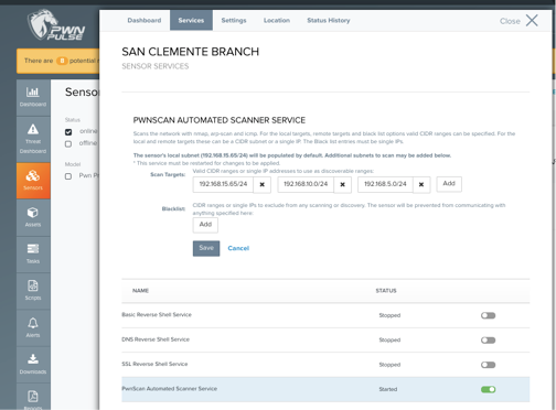
To add remote targets to the PwnScan automated scanning service:
- Log into Pulse.
- Select the Sensors from the left-hand toolbar, and select the sensor to be configured.
- Select the Services tab, and click on the text for PwnScan Automated Scanner Service.
- Enter IP ranges in CIDR notation for each target subnet/VLAN.
- Click Save.
- Start the PwnScan service using the toggle. If PwnScan was already running, restart by toggling the service off and on.
Note
When scanning a new network for the first time, it may take up to several hours for the scan to populate data in Pulse, depending on the network size.
Planning and Support
Network equipment, configurations and requirements can vary. Consult with one of Pwnie Express’ Security Engineers to discuss how best to monitor your network. Contact the Support for more information.
Copyright
© 2025 Outpost24® All rights reserved. This document may only be redistributed unedited and unaltered. This document may be cited and referenced only if clearly crediting Outpost24® and this document as the source. Any other reproduction and redistribution in print or electronically is strictly prohibited without explicit permission.
Trademark
Outpost24® and OUTSCAN™ are trademarks of Outpost24® and its affiliated companies. All other brand names, product names or trademarks belong to their respective owners.